
While it can be fun to have all sorts of locomotives on your layout (or your collection), the path to realism is to model what was common, ordinary, rather than the odd or unusual.
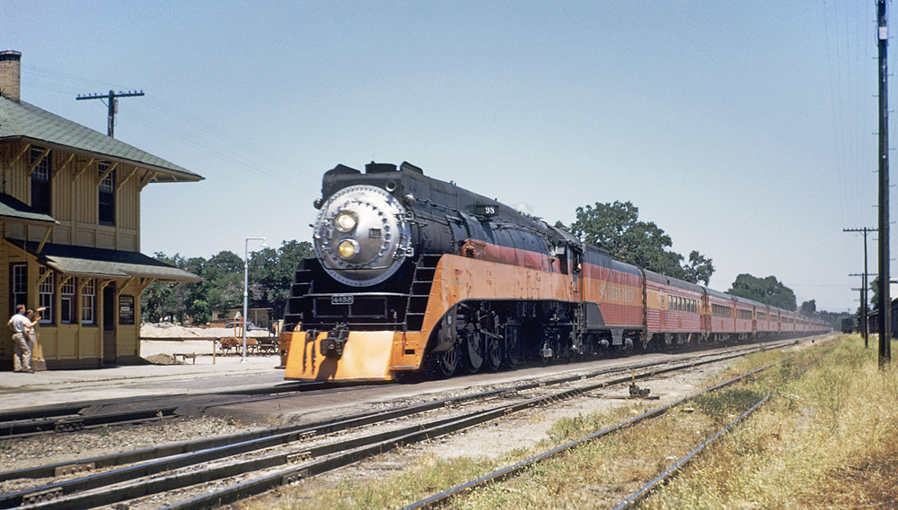
I model the Southern Pacific Coast Line in 1953. Why the Coast Line? Well, this is the route of “The Most Beautiful Train in the World,” Southern Pacific’s Daylight. And why 1953? Well, in 1955, Southern Pacific’s gorgeous GS-4 and GS-5 streamlined 4-8-4s were replaced by EMD E units. So I knew I didn’t want to model any later that. As Tony Thompson points out on his blog, 1953 was the last year steam dominated the Coast Division. I found that a very compelling argument. More specifically, I like helper operations – the challenges of mountain railroading. So my (eventual) layout will focus on Cuesta Grade, the line going north from San Luis Obispo to Santa Margarita, California.
Models I will be presenting here are, for the most part, representative of that era and location. However, I’ve got a few other things in mind to share, so “stay tuned!”


